Digital Joinery For Hybrid Carpentry
- 2 בפבר׳ 2018
- זמן קריאה 2 דקות
עודכן: 12 במרץ 2024

With Shiran Magrisso, Moran Mizrahi, 2017
The craft of carpentry relies on joinery: the connections between pieces of wood to create multipart structures. In traditional woodworking, joints are limited to the manual chisel skills of the craftsperson, or to capabilities of the machines, which favorite 90° or 180° angle joints with no more than two elements. We contribute an interactive design process in which joints are generated digitally to allow for unrestricted beam connectors, then produced from Nylon-12 using selective laser sintering (SLS) 3D printing. We present our Generative Joinery Design Tool and demonstrate our system on a selection of stools. This project exemplifies the potential of Digital Joinery to enhance carpentry by incorporating a hybrid and interactive level of design sophistication and affordances that are very hard to achieve with traditional skills and tools.
Research papers
Magrisso, S., & Zoran, A. P. (2019). Digital Joinery For Hybrid Carpentry. In F. Bianconi & M. Filippucci (Eds.), Digital Wood Design: Innovative Techniques of Representation in Architectural Design. Springer.
Magrisso, S., Mizrahi, M., & Zoran, A. P. (2018). Digital Joinery For Hybrid Carpentry. In Proceedings of the 36th International Conference on Human Factors in Computing Systems (CHI '18). ACM. Honourable Mention Award. https://doi.org/10.1145/3173574.3174035


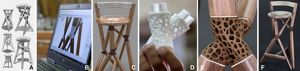
Five development stages of a hybrid stool. (A) An early sketch of a stool design relying on Digital Joinery; (B) using the Generative Joinery Design Tool, the software generates digital joints; (C) a rendering of a complete stool with digital joints; (D) a 3D-printed (by selective laser sintering) Nylon-12 joint with its anchors; (D) a closeup photograph of a dyed and assembled Voronoi diagram skeleton joint, connecting four wooden beams; (E) a photograph of the finished stool (by Daniel Shechter).
The interactive procedure and workflow of our Generative Joinery Design Tool (GJDT). (A) Specifying lumber position in Rhino; (B) selecting surfaces to be joined in GJDT; (C) defining the position and orientation of the supporting contour curves, (C1) and controlling their fillet angles; (D) applying a loft function between the surfaces to create a watertight solid object; (E) populating this object with random points, or (E1) using attractor points; (F) generating a 3D Voronoi diagram with or without isocurves; (G) creating a solid 3D Voronoi skeleton in the arm thickness defined by the user; and (I) outputting the design for external structural validation tests.

תגובות